Electric Gate Sensor Repair: Safety Beam Alignment and Troubleshooting Guide
Misaligned safety beams are the most common reason an automatic gate stops, reverses, or refuses to close. This guide explains how to diagnose, align, and repair those photocell sensors yourself—saving time and money while keeping your gate safe and compliant.
- First step: Misaligned sensors are the most common cause of a gate that stops or reverses unexpectedly.
- Safety first: Always disconnect power before working on sensors to avoid electrical shock.
- Precision required: Proper alignment requires both sensors to face each other precisely, with a clear line of sight.
- Know when to replace: If alignment fails after multiple attempts, check wiring, brackets, or consider replacement.
- Never bypass: Never bypass safety beams—they are critical for preventing crushing injuries.
How Safety Beams Work: The Basics of Electric Gate Sensor Repair
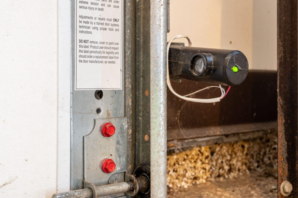
Electric gate safety beams, also called photocell sensors, consist of a transmitter and a receiver mounted on opposite sides of the gate opening. The transmitter sends an invisible infrared beam to the receiver. When the beam is broken by an obstruction, the gate controller immediately stops or reverses the gate. This system is required by the UL 325 safety standard for automatic gate operators.
Most residential and commercial gates use through-beam sensors, where the two units must be in direct line of sight. Some systems use reflective sensors, but through-beam is more reliable for outdoor use. The sensors are typically connected to the gate opener with low-voltage wiring (usually 12V to 24V DC).
Signs Your Sensors Need Repair
How do you know if your safety beams are misaligned? Look for these symptoms:
- The gate stops mid-cycle and then reverses.
- The gate closes but then reopens immediately.
- The gate will only close when you hold the remote button continuously.
- The sensor LED is off, dim, or flashing instead of steady.
- The gate works fine at night but has issues during bright sunlight.
If you notice any of these, start with a visual check. Look at the sensor LEDs. On most systems, a steady green or red LED indicates normal operation. A flashing or off LED points to alignment or power problems.
Tools and Materials for Electric Gate Sensor Repair
Before you start, gather these items:
- Screwdriver (Phillips or flathead, depending on your bracket screws)
- Measuring tape
- Small level
- Multimeter (for voltage and continuity tests)
- Wire strippers and connectors (if you need to repair wiring)
- Sun shades (if glare is an issue)
- Replacement sensor set (if alignment fails repeatedly)
Step-by-Step Sensor Alignment Procedure
1. Disconnect Power
Always unplug the gate opener or turn off the circuit breaker before touching any wiring. This prevents electrical shock and accidental gate movement.
2. Clean the Sensors
Wipe the lens of each sensor with a soft, dry cloth. Dirt, spider webs, or frost can block the beam. Even a thin layer of grime can cause false obstruction signals.
3. Check the Brackets
Inspect the mounting brackets. They should be firmly attached to the gate posts or fence. Tighten any loose screws. If a bracket is bent or rusted, replace it. A stable bracket is essential for maintaining alignment over time.
4. Rough Align the Sensors
Loosen the screws on both sensor brackets just enough to allow movement. Point the transmitter and receiver directly at each other. Use a level to ensure both are vertical and at the same height above the ground. Typically, sensors are mounted 6 to 12 inches above the ground, but check your manufacturer’s manual.
Suggested read: Electric Gate Repair: Troubleshooting & Solutions Guide
5. Fine-Tune the Alignment
Tighten one sensor fully. Then, while watching the receiver’s LED, slowly adjust the other sensor. Move it left, right, up, and down in small increments. When the LED turns steady (green or red depending on the model), you have achieved alignment. Repeat this process for the other sensor if needed.
If your system has a test button on the receiver, press it to confirm the beam is intact. Some controllers also have a diagnostic mode that flashes the LED in a specific pattern when alignment is correct.
6. Secure and Test
Once the LED is steady, tighten all bracket screws firmly. Reconnect power and test the gate. Walk through the beam path while the gate is closing. The gate should stop and reverse immediately. If it doesn’t, repeat the alignment steps.
Testing Sensors and Wiring for Electrical Issues
If alignment doesn’t solve the problem, the issue may be electrical. Here’s how to test the wiring and power.
Voltage Test
Set your multimeter to DC volts. Place the probes on the power terminals of the receiver sensor. You should see a reading between 12V and 24V, depending on your system. If the voltage is zero or very low, the problem is in the wiring from the gate opener to the sensor.
Continuity Test
Disconnect the wires from the sensor and the gate controller. Use the multimeter’s continuity setting to check each wire. If there is no continuity, the wire is broken or has a bad connection. Repair or replace the damaged wire.
Check for Shorts
Inspect the wire insulation for cuts or abrasions. Exposed copper can short against the gate frame, causing erratic behavior. Use electrical tape or heat shrink tubing to repair damaged sections. If the wire runs underground, look for signs of rodent damage or water intrusion.
Common Problems and Fixes in Electric Gate Sensor Repair
Sun Glare and False Triggers
Bright sunlight can overwhelm the receiver, especially when the sun is low on the horizon. This causes the gate to reverse at the same time each day. The fix is simple: install sun shades on the sensors. These are small hoods that block direct light while allowing the beam to pass. Many manufacturers offer shades as accessories, or you can make your own from black plastic.
Loose or Bent Brackets
Vibration from the gate, wind, or accidental bumps can loosen brackets over time. Check them monthly. If a bracket is bent, straighten it with pliers or replace it. Use lock washers or thread-locking compound on the screws to prevent future loosening.
Wire Damage
Exposed wires are vulnerable to lawnmowers, trimmers, and weather. If you find a cut or frayed wire, splice it using waterproof connectors. For underground runs, use direct-burial-rated cable. Always leave a service loop at each end so you can make repairs without pulling new wire.
Internal Sensor Failure
If the sensor LED is off and voltage is present at the terminals, the sensor itself may be dead. This is more common with cheaper units or after a lightning strike. Replace both sensors as a pair, even if only one appears faulty. Mixing old and new sensors can cause compatibility issues.
Suggested read: Electric Gate Troubleshooting: Identifying and Fixing Common Issues
When to Call a Professional for Electric Gate Sensor Repair
Some situations require a licensed gate technician:
- You have tried alignment and wiring tests, and the problem persists.
- You see visible damage to the gate opener circuit board or wiring.
- The gate has a history of crushing incidents or near-misses.
- You are uncomfortable working with low-voltage wiring or climbing ladders near the gate.
- Your gate system is complex, such as a commercial barrier or a sliding gate with multiple sensors.
A professional will have specialized tools like a laser alignment tool and a signal strength meter. They can also verify that your system meets UL 325 requirements, which is important for insurance and liability purposes.
Preventive Maintenance Tips
Prevent sensor issues before they start with these simple habits:
- Clean the sensor lenses monthly with a soft cloth.
- Check bracket tightness every season.
- Trim vegetation that could grow in front of the sensors.
- Test the safety system weekly by placing an object (like a cardboard box) in the gate’s path.
- Replace batteries in wireless sensors annually.
- Keep a spare sensor set on hand for quick replacement.
Many gate opener manufacturers, including LiftMaster, Chamberlain, Linear, and Mighty Mule, provide detailed maintenance schedules in their manuals. Following those guidelines extends the life of your gate system.
Frequently Asked Questions
How do I know if my safety beams are misaligned?
The gate stops mid-cycle or reverses unexpectedly, and the sensor LED may be off or flashing. A steady LED usually means alignment is correct.
What tools do I need to realign electric gate sensors?
A screwdriver, measuring tape, level, and possibly a multimeter for wiring tests. Sun shades may also be needed if glare is an issue.
What are the common causes of sensor misalignment?
Vibration from the gate, weather (wind, rain, snow), loose brackets, sun glare, or physical obstruction like weeds or spider webs.
How do I test the sensor wiring and power?
Use a multimeter to check for correct voltage at the sensor terminals (typically 12V to 24V DC) and inspect wires for damage or breaks. Perform a continuity test on each wire.
When should I replace the sensors instead of realigning?
If alignment fails after multiple attempts, or if there is visible damage, corrosion, or internal failure (LED off despite power present). Replace both sensors as a pair.
How do sun shades and mounting brackets affect alignment?
Sun shades reduce false triggers from glare, and stable brackets maintain consistent alignment. Loose or bent brackets are a leading cause of misalignment.
What safety precautions must I take during repair?
Disconnect gate opener power before touching any wiring. Never bypass safety beams. Follow UL 325 guidelines, which require functional sensors for automatic closing gates. If you are unsure, hire a professional.
Suggested read: Choosing a Professional for Electric Gate Repair: What to Look For
Conclusion
Misaligned safety beams are a common but fixable problem for electric gate owners. By following the step-by-step alignment procedure and testing the wiring, you can often restore reliable operation in under an hour. Remember to prioritize safety: disconnect power, never bypass the sensors, and consult UL 325 for compliance. Regular maintenance—cleaning lenses, tightening brackets, and testing the system—will keep your gate running safely for years. If the issue persists despite your best efforts, don’t hesitate to call a certified gate technician.
For more detailed guidance, refer to your gate opener’s manual or the National Electrical Code articles on low-voltage wiring. A well-maintained gate is a safe gate.
Related Articles
- Electric Gate Opener Troubleshooting Guide
- Understanding Automatic Gate Safety Sensors
- Gate Opener Wiring Repair and Maintenance
- UL 325 Compliance Checklist for Gate Operators
- Sliding Gate Sensor Alignment Tips
Sources and References
- UL 325 Standard for Safety for Door, Drapery, Gate, Louver, and Window Operators and Systems
- ASTM F2200 Standard Specification for Automated Vehicular Gate Construction
- National Electrical Code (NEC) Article 725: Class 1, Class 2, and Class 3 Remote-Control, Signaling, and Power-Limited Circuits
- LiftMaster Gate Operator Installation Manuals
- Chamberlain Group Technical Support Documentation
- Linear Gate Operator Service Guides
- Mighty Mule Gate Opener User Manuals